|
 The XF8U-1 was powered by a Pratt & Whitney J57-P11 powerplant, capable of delivering 9,700 pounds of static thrust at sea level, and 14,800 pounds in afterburner. The wing of the aircraft had a span of 35 feet 8 inches, a sweep of 42 at the one quarter chord, and an area of approximately 350 square feet, by far the largest wing on any single engine fighter aircraft at the time. The outer wing panels folded approximately 90 degrees at approximately mid span, powered by the utility hydraulic system, and locked in the spread position. In plan form, the leading edge of the wing had a sawtooth step at the wing fold - the outer panel leading edge extended approximately 8 inches forward of the center section leading edge. The entire leading edge of the wing, from the fuselage intersection to the tip, was hinged and could be powered down to form a leading edge droop. The trailing edge of the wing center section was hinged in two sections, the inboard portion as a flap, and the outer portion as the aileron. There were no control surfaces on the wing outer panel. The XF8U-1 was powered by a Pratt & Whitney J57-P11 powerplant, capable of delivering 9,700 pounds of static thrust at sea level, and 14,800 pounds in afterburner. The wing of the aircraft had a span of 35 feet 8 inches, a sweep of 42 at the one quarter chord, and an area of approximately 350 square feet, by far the largest wing on any single engine fighter aircraft at the time. The outer wing panels folded approximately 90 degrees at approximately mid span, powered by the utility hydraulic system, and locked in the spread position. In plan form, the leading edge of the wing had a sawtooth step at the wing fold - the outer panel leading edge extended approximately 8 inches forward of the center section leading edge. The entire leading edge of the wing, from the fuselage intersection to the tip, was hinged and could be powered down to form a leading edge droop. The trailing edge of the wing center section was hinged in two sections, the inboard portion as a flap, and the outer portion as the aileron. There were no control surfaces on the wing outer panel.
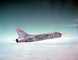
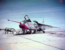
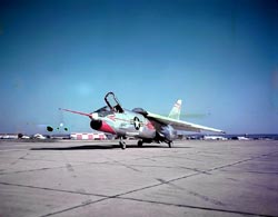 Of all the innovations designed into the Crusader, the two-position wing was one of the simplest and at the same time provided many tremendous benefits. The wing was hinged on the rear spar, and was raised 7 degrees by an internally self-locking hydraulic actuator attached to the starboard front spar. When the pilot actuated the wing unlock handle on the starboard console, the wing actuator unlocked and started the wing toward the up position. This same motion unlocked the leading edge droop actuators and extended the droops down 25 degrees to the land position. As the wing moved through its 7 degrees of arc, a mechanical linkage repositioned the trailing edge flap and aileron down 20 degrees. The combination of the extended leading edge droops and the drooped flaps and ailerons gave the wing an increased camber and a significantly increased coefficient of lift. While the aircraft was on the ground, it was pretty evident that the wing moved from the down to the up position. However, in flight, there was an ongoing dispute as to whether the wing moves to the up position, or since the wing is the lifting surface of an aircraft in flight, it actually pushes the fuselage to the down position. As the wing moved through its 7 degrees of travel, an electrical signal caused the horizontal tail surfaces to be repositioned to correspond to the wings angle of attack and maintain level flight. The net result of this repositioning of the wing was excellent visibility for the pilot during his approach to landing. The resulting position of the fuselage, more level to the deck at takeoff and landing, permitted the design of a shorter, lighter landing gear providing enhanced accessibility for maintenance. Of all the innovations designed into the Crusader, the two-position wing was one of the simplest and at the same time provided many tremendous benefits. The wing was hinged on the rear spar, and was raised 7 degrees by an internally self-locking hydraulic actuator attached to the starboard front spar. When the pilot actuated the wing unlock handle on the starboard console, the wing actuator unlocked and started the wing toward the up position. This same motion unlocked the leading edge droop actuators and extended the droops down 25 degrees to the land position. As the wing moved through its 7 degrees of arc, a mechanical linkage repositioned the trailing edge flap and aileron down 20 degrees. The combination of the extended leading edge droops and the drooped flaps and ailerons gave the wing an increased camber and a significantly increased coefficient of lift. While the aircraft was on the ground, it was pretty evident that the wing moved from the down to the up position. However, in flight, there was an ongoing dispute as to whether the wing moves to the up position, or since the wing is the lifting surface of an aircraft in flight, it actually pushes the fuselage to the down position. As the wing moved through its 7 degrees of travel, an electrical signal caused the horizontal tail surfaces to be repositioned to correspond to the wings angle of attack and maintain level flight. The net result of this repositioning of the wing was excellent visibility for the pilot during his approach to landing. The resulting position of the fuselage, more level to the deck at takeoff and landing, permitted the design of a shorter, lighter landing gear providing enhanced accessibility for maintenance.
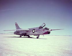 The landing gear was a tricycle type gear, housed totally within the fuselage. The left and right hand main gear, located in the center fuselage section, consisted of a tension strut and an oleo type shock strut, with a combination drag strut/actuator attached to the lower end of the shock strut. The gear retracted forward into the gear well, and was enclosed by doors which closed flush and smooth with the fuselage. The steerable nose gear was mounted in the lower nose section, slightly aft of the cockpit, and under the engine air duct. This gear retracted aft, powered by a combination drag strut/actuator. The landing gear was a tricycle type gear, housed totally within the fuselage. The left and right hand main gear, located in the center fuselage section, consisted of a tension strut and an oleo type shock strut, with a combination drag strut/actuator attached to the lower end of the shock strut. The gear retracted forward into the gear well, and was enclosed by doors which closed flush and smooth with the fuselage. The steerable nose gear was mounted in the lower nose section, slightly aft of the cockpit, and under the engine air duct. This gear retracted aft, powered by a combination drag strut/actuator.
The total fuel capacity of the XF8U-1 was 1188 U.S. gallons, 8,033 pounds of JP-5 jet fuel. The main tank was located in the fuselage, immediately forward of the main landing gear wells, wrapped around the engine air inlet duct. The main fuel cell held 440 gallons (2,963 pounds), and contained four electrically driven pumps which supplied fuel under pressure to the engine during upright flight, and two inverted flight pumps which operated when the aircraft exceeded an attitude of 13 nose up, 10 nose down or a roll attitude exceeding 10. The transfer system held a total of 748 gallons (5070 pounds), 574 gallons (3901 pounds) in the wing center section (this in spite of a statement in the first Aviation Week magazine description of the Crusader to the effect that the wing is obviously too thin to contain any fuel) and 174 gallons (1169 pounds) in a cluster of four fuel cells , shielded with double- walled titanium air cooled panels aft of the fire wall in the engine compartment. All fuel from the transfer system was pumped into the main fuel cell in a programmed sequence to maintain the center of gravity within aerodynamic limits. All fuel cell cavities were pressurized by engine bleed air or ram air to prevent fuel boiling at high altitude.
The hydraulic systems in the Crusader consisted of two power control systems, PC-1 and PC-2, and the Utility system. Each of the systems was pressurized to a nominal 3,000 psi by its own pump, mounted on an engine-driven gear box attached to the lower forward portion of the powerplant. Each of the systems was entirely separate, a closed system with a reservoir to maintain constant availability of fluid during high demand operations. The two PC systems powered all of the flight control surfaces, ailerons, horizontal tails and rudder. Each surface was controlled by a tandem actuator, one half powered by PC-1, the other half by PC-2. Pilot input by stick or pedal movement was mechanically transmitted to a slider valve attached to the actuator. The slider valve piston was repositioned in accordance with pilot input to allow fluid flow into the cylinder to reposition the piston which was directly attached to the surface. With both PC systems supplying muscle to the surface, is was capable of controlling the flight of the aircraft, no matter what the aerodynamic loads on the surface. In the event of failure to one system or the other, the remaining system had the capability of controlling the aircraft to a safe landing. A Marquardt ram air turbine (RAT) was provided on the lower starboard side of the fuselage. In the event of a dual PC system failure, the RAT could be deployed into the airstream where it would drive its own hydraulic pump to pressurize the PC-1 system to give very limited control of the aircraft in an emergency landing. This procedure was usable only if the PC-1 system was intact (i.e. the system had not lost its fluid). There were several instances during the life of the Crusader where this procedure was used to land a disabled aircraft.
 The Utility Hydraulic System, also pressurized by a pump on the engine-driven gear box, was a closed system with its own reservoir and was also pressurized to 3,000 psi. This system operated the landing gear, the arresting gear, the wing incidence with its associated leading edge droops, the speed brake , wheel brakes, the nose gear steering, outer panel wing fold and lock and, on later models , the inflight refueling probe. In case of a Utility System failure, a back-up pneumatic system was provided which allowed one-time operation of critical systems to permit emergency return to base. The nose landing gear was powered to the down-and-locked position, and the main landing gear was unlocked from its retracted position, from which gravity and ram air pressure forced it to its down-and-locked position. The arresting gear was powered to its extended position. The wing incidence and leading edge droops were extended to the landing position. Limited braking was available during landing rollout. The Utility Hydraulic System, also pressurized by a pump on the engine-driven gear box, was a closed system with its own reservoir and was also pressurized to 3,000 psi. This system operated the landing gear, the arresting gear, the wing incidence with its associated leading edge droops, the speed brake , wheel brakes, the nose gear steering, outer panel wing fold and lock and, on later models , the inflight refueling probe. In case of a Utility System failure, a back-up pneumatic system was provided which allowed one-time operation of critical systems to permit emergency return to base. The nose landing gear was powered to the down-and-locked position, and the main landing gear was unlocked from its retracted position, from which gravity and ram air pressure forced it to its down-and-locked position. The arresting gear was powered to its extended position. The wing incidence and leading edge droops were extended to the landing position. Limited braking was available during landing rollout.
Electrical power was provided by a 12-kva generator also mounted on the engine-driven gear box. A transformer converted AC power to DC for those systems that required it. Wire harnesses distributed this power to all parts of the aircraft. In the event of a main generator failure, the Marquardt RAT could be deployed to obtain limited electrical power for an emergency return to base.
More F8U:
XF8U-1 Innovative Systems
XF8U-1 In the Cockpit
A New Aircraft and a New Corporation
F8U-1 and F8U-1E Production Aircraft Changes
Life Extension
Loss of XF8U-3 Contract and a New Challenge
Last Flight - December 1999
|