|
FUSELAGE FABRICATION
General Description - Materials
The O3U-3 fuselage primary structure is a welded space frame constructed from 4130 tube steel. The forward portion of the fuselage is skinned in sheet aluminum. The aft portion, from the aft cockpit to the tail, is covered in fabric. The fabric is stretched over and is attached to longitudinal wood stringers. The stringers attach to frames fabricated from aluminum plate. Saddle fuel tanks on each side of the cockpit were fabricated from sheet aluminum and locally form the OML surface of the fuselage.
Steel Truss Frame Weldment
Original O3U-3 drawings were used to fabricate the steel truss frame. Tube diameter for the upper and lower longitudinal members is 1.10" in the forward and cockpit area and 1.00" reducing to 0.875" going aft. Vertical and diagonal members are 0.875" and 0.563" diameter.
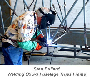 Stan Bullard built the truss frame, including all of the welding. A long tooling table was set up to provide a level platform on which to layout and weld the frame members. This table consisted of plywood sheet on top of a wood base. An aluminum plate was placed over the plywood. The aluminum plate was shimmed as needed to provide a level tool surface. Stan Bullard built the truss frame, including all of the welding. A long tooling table was set up to provide a level platform on which to layout and weld the frame members. This table consisted of plywood sheet on top of a wood base. An aluminum plate was placed over the plywood. The aluminum plate was shimmed as needed to provide a level tool surface.
The frame top members and connecting trusses were built first. Using the O3U-3 frame drawing, the coordinate points of all of the tube intersections were marked on the aluminum plate. Tube holder brackets were attached to the aluminum plate. Tube members were positioned on the aluminum plate and all of the joint intersections were welded. The frame bottom truss was built in a similar manner.
With the bottom truss in position on the aluminum plate, the upper truss was positioned into the correct vertical location. It was held in place with temporary supports attached to the aluminum tooling plate. Vertical and diagonal tubes were then welded between the upper and lower trusses. Attach brackets for the wings, pontoon, engine, saddle tanks, and controls were then welded to the frame.
Bulkheads and Stringers
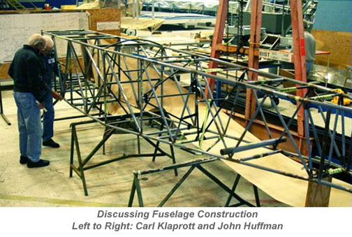
Aluminum bulkheads (0.080 inch thick) were fabricated and installed in the aft fuselage to support the wood stringers. These bulkheads attach to the fuselage truss frame, and can be seen in the photograph below. These bulkheads in the original O3U-3 were fabricated from 3/16 inch thick plywood. The stringers in the photo are temporary aluminum stringers, used to develop the OML contour and to locate the stringer notches to be cut into the bulkheads. Wood stringers will be fabricated, placed in the bulkhead stringer notches, and attached to each bulkhead.
Nose and Cockpit Aluminum Skins
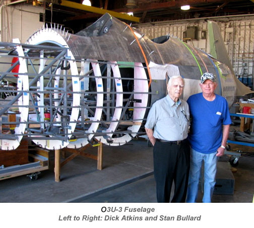
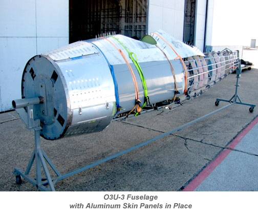
Aluminum skin panels were fabricated for the fuselage forward section between the engine and the cockpit, and for the upper fuselage area around the cockpits, as shown below. Skin panels are 0.032 in. thick. Louvers were stamped in the forward section skin panels using a louver die.
Fuel Saddle Tanks
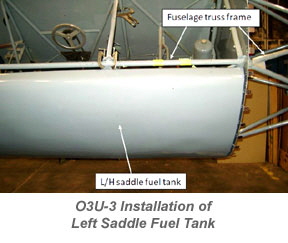 Twin fuel tanks are located on each side of the cockpit. The geometry and dimensions of these tanks were constructed according to the O3U-3 original drawings. Outer skins are sheet steel and the end bulkheads and eight vertical ribs were fabricated from aluminum (outer skins of the original O3U-3 tanks were made from aluminum and all seams were welded). The tanks are 68 inches long, 28 inches high, and 8.25 inches maximum width. Each tank holds 68 gallons. Twin fuel tanks are located on each side of the cockpit. The geometry and dimensions of these tanks were constructed according to the O3U-3 original drawings. Outer skins are sheet steel and the end bulkheads and eight vertical ribs were fabricated from aluminum (outer skins of the original O3U-3 tanks were made from aluminum and all seams were welded). The tanks are 68 inches long, 28 inches high, and 8.25 inches maximum width. Each tank holds 68 gallons.
A wood mold shaped to the fuel tank outer skin contour was fabricated. The steel skins were heated and then wrapped around the wood mold. Small steel angles were riveted to the internal ribs. The steel angles were than welded to the outer skins. The wood mold and fuel tanks were fabricated by Stan Bullard.
COCKPIT INSTALLATIONS
Cockpit Controls
The O3-U3 has a dual, tandem cockpit configuration. Both cockpits have stick and rudder controls, engine throttles, and flight instruments. Dillon Smith was led the cockpit and controls fabrication team.
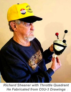
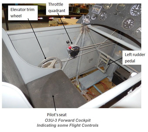
The throttle quadrant, located on the left side of the front cockpit, has three levers: engine throttle, carburetor mixture control, and spark advance control. The rear cockpit has only a throttle.

Pilot’s Sticks and Rudder Pedals
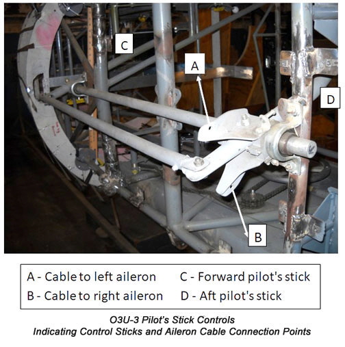
Both forward and aft cockpits have interconnected pilot's sticks and rudder pedals. The pilot's stick (forward and aft) and connecting parts were fabricated by Dillon Smith. Aluminum tubing and 0.125 in. thick aluminum flat stock were used. The shaft connecting forward and aft sticks is steel. Controls were fabricated according to O3U-3 drawings a closely as possible. The pilot's stick in the aft cockpit can be removed and stowed in-flight so that it does not hinder operations of the rear facing machine gun.
Stick control rods below seats connect to cables which activate the ailerons and elevator. Rudder pedals were also fabricated from aluminum, and attach to cables which activate the rudder.
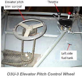
An elevator pitch trim control wheel is located on the left side of the forward cockpit. The wheel drives a sprocket and chain mechanism which is attached to cables aft of the cockpit. Near the elevator, the cables turn a jackscrew which is attached to the elevator. Aircraft pitch trim angle is changed by rotating the elevator on its hinged supports.

Instrument Panels
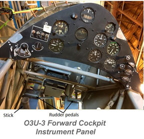
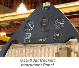
Cockpit instrument panels were fabricated by Bob Essler, Richard Sheaner, and Huey Barrilleaux. They were fabricated using O3U-3 drawings. Most instruments were purchased used from various sources. Replica instruments were fabricated for those that could not be found.
Pilot’s Seats
The pilot seats were fabricated by Dillon Smith, and are made from 0.063 in. thick aluminum. They were fabricated using original O3U-3 drawings. The seats were constructed from four pieces (bottom, back, and two sides) riveted together.
Seats have bottom and back cushions made of foam and covered with black naugahyde material. The cushions were fabricated by Bill's Trim Shop in Arlington, Texas. The front seat back support is slightly curved and was made from 0.25 in. thick plywood. Partial thickness vertical saw cuts were made in the plywood so that it would bend to the curved shape.
The front seat is adjustable fore-aft by pulling a pin. The back seat is not adjustable. The seat bottom folds up and latches to provide room for the aft pilot to use the rear facing machine gun.
Cockpit Windshields
Dimensioned drawings of the forward and aft cockpit windshields were made from O3U-3 drawings. These dimensioned drawings are being used by Grand Prairie Glass and Mirror Company to fabricate the windshields, which are formed from 0.150 in. thick Plexiglas. The windshield transparencies will be mounted in aluminum frames. The aft windshield is hinged at the bottom and folds forward.
Page 4 of 6

|